
 OBRALIA
3DCP printed piece
Digitally manufactured modules forming the inner and/or outer face of the wall.
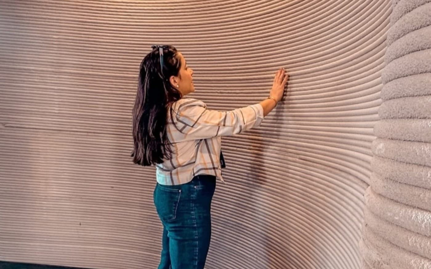
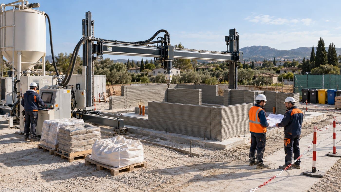
A printer deposits layers of concrete mortar following a digital model. This builds walls with free geometry, less formwork and less manual work on site.
Four questions, one minute. We tell you which system fits your case best and why.
What do you want to build?
The design becomes layer-by-layer print paths.
Technical mortar, dosed and checked before pumping.
The nozzle lays the concrete bead layer upon layer.
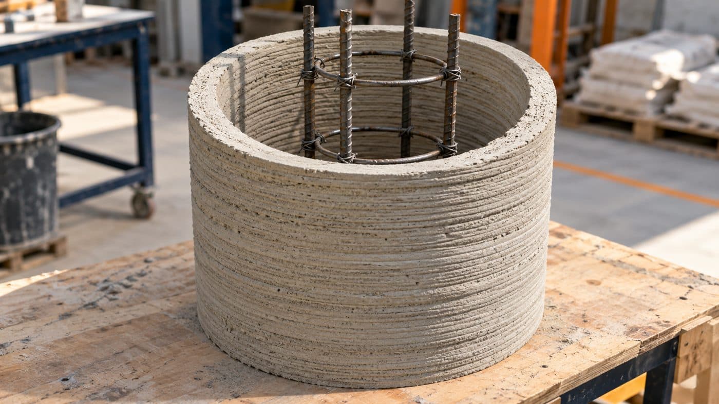
Reinforcement, services and openings are integrated as designed.
Roof, joinery, services and final finish.
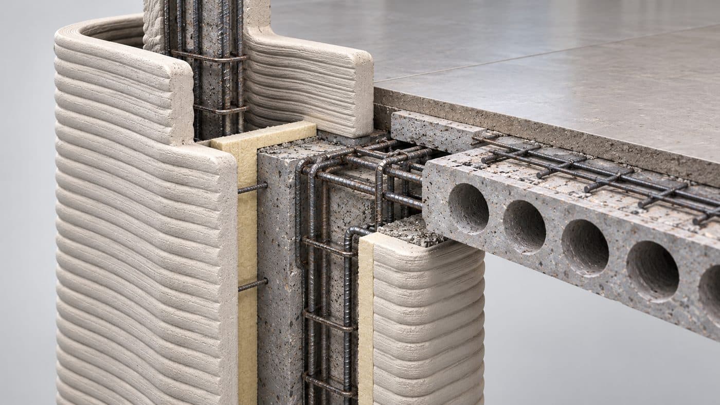
It is not an isolated mortar wall: it is a building system. The printed shell acts as permanent formwork and the reinforced-concrete core carries the structural load.
Digitally manufactured modules forming the inner and/or outer face of the wall.
Reinforced concrete designed to the Spanish CTE, integrated in the cavity between the printed faces.
Continuous, durable surface with colour in the mix and no later finishing steps.
Printed walls do not replace structural design: the reinforced core and foundations are designed and professionally endorsed as in any reinforced-concrete building.
Key junctions of a printed wall: foundation, insulation, services and slab. Illustrative diagrams; the actual design is set by the execution project under the Spanish CTE.
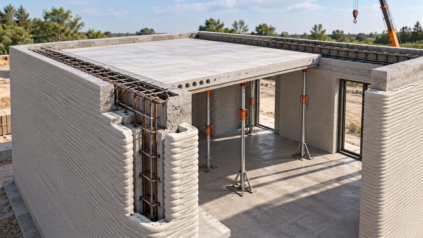
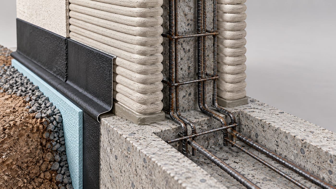
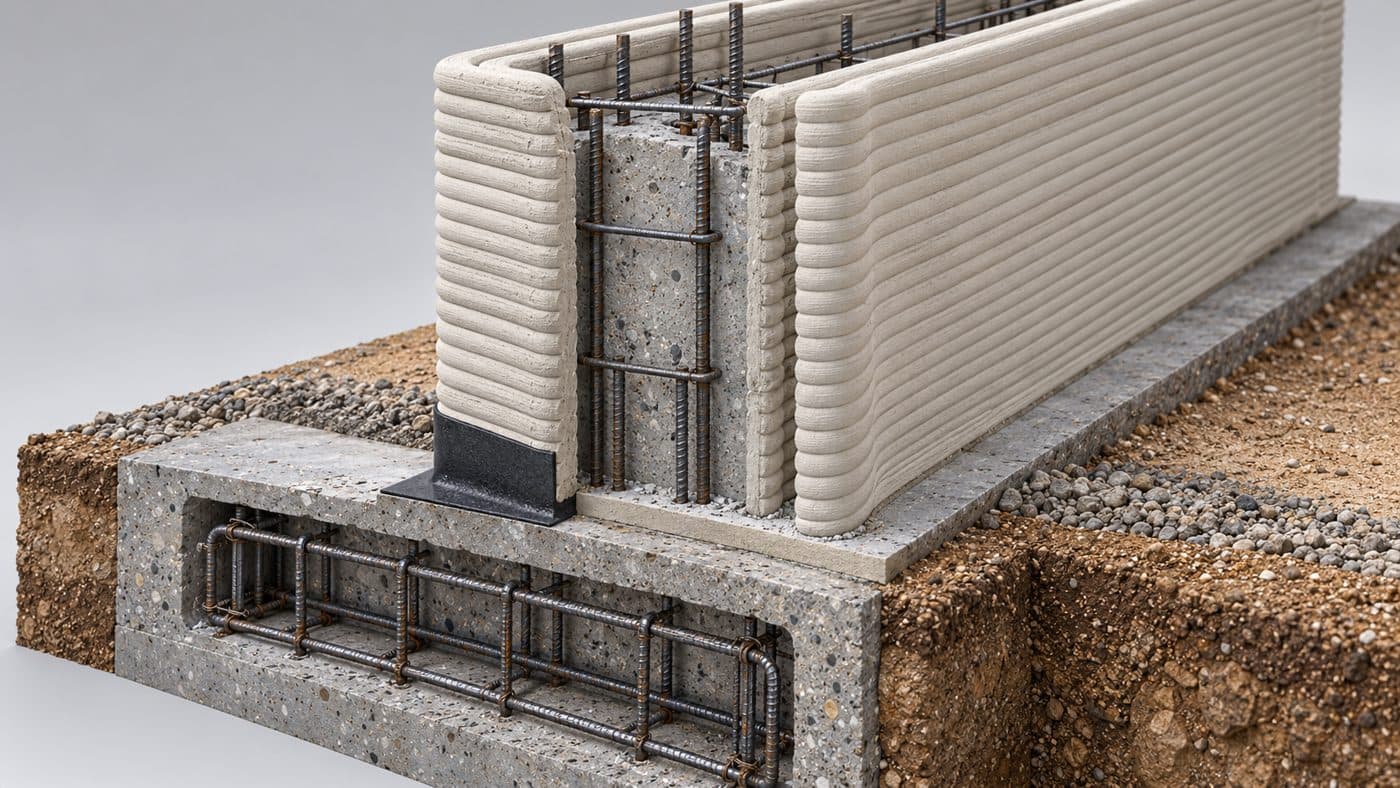
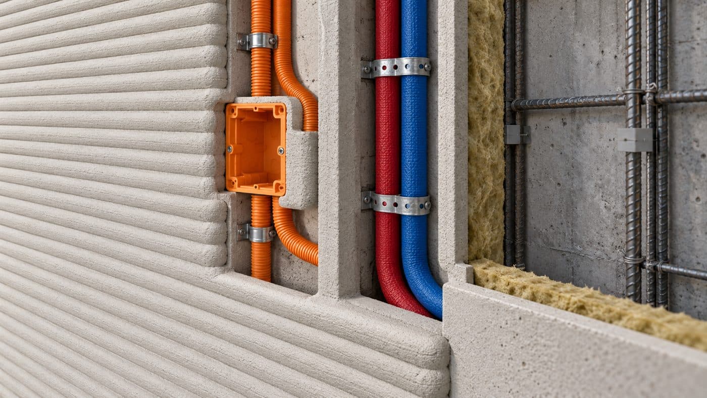
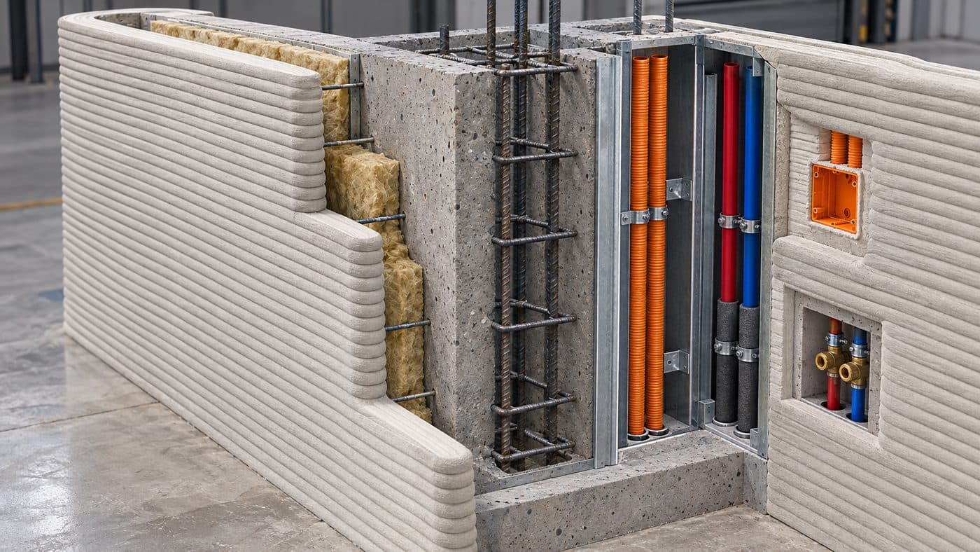
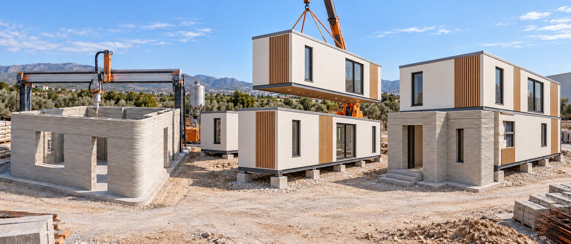
Illustrative, digitally generated visualizations; they do not depict completed works.
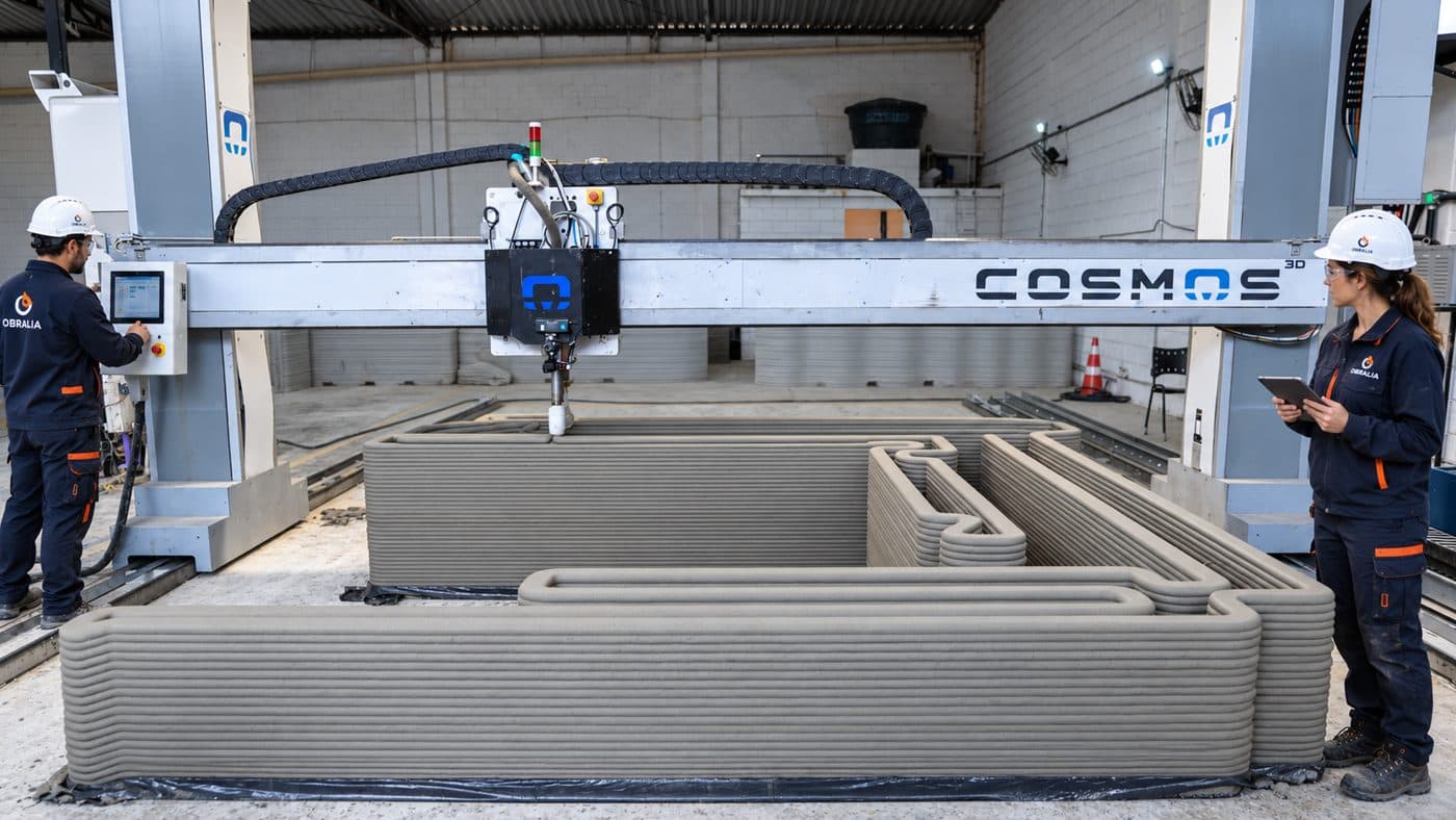
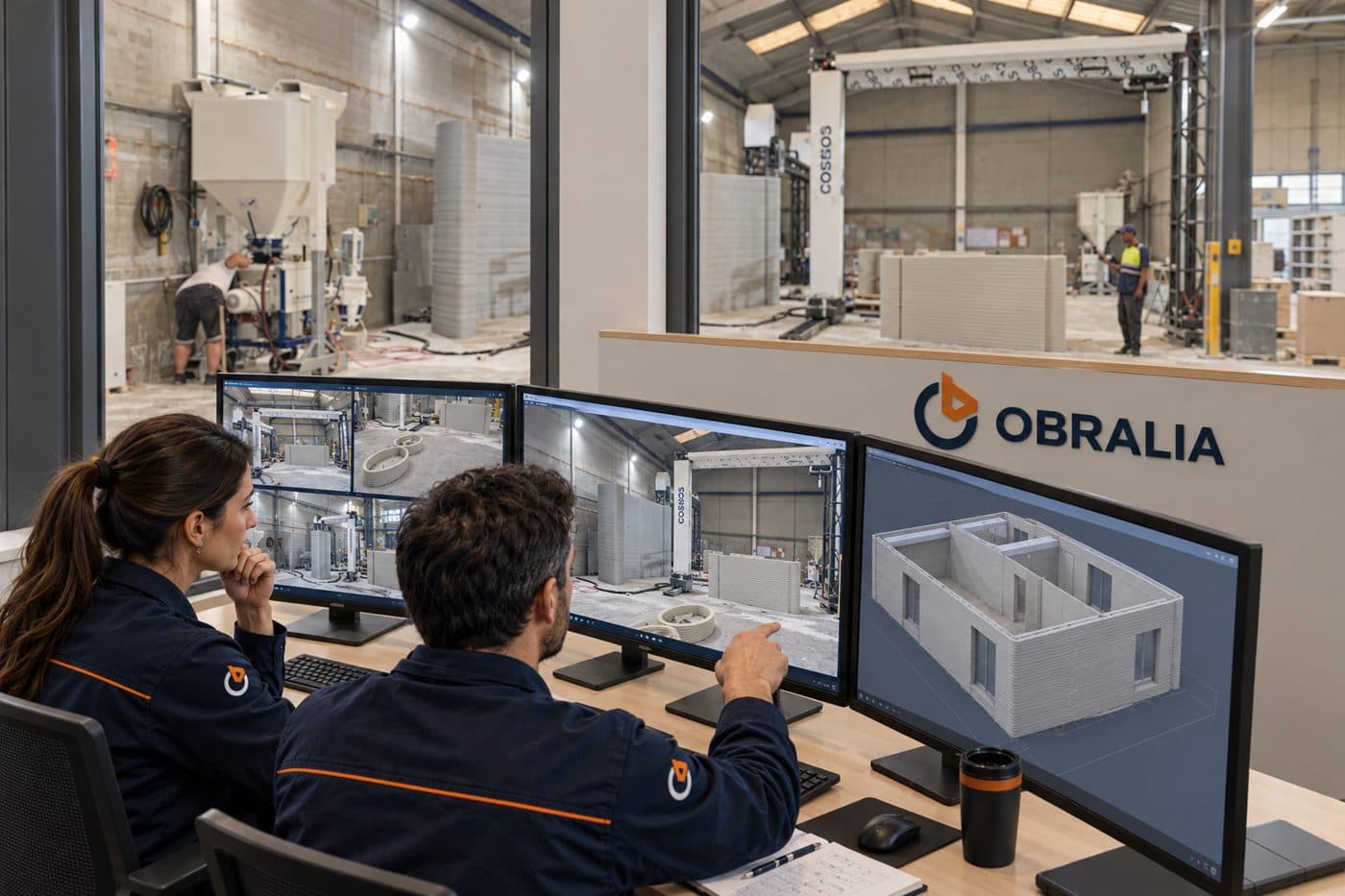
Robotic gantry with a continuous mixing and pumping system. Data published by the manufacturer.
| Manufacturer | Cosmos 3D · Puerto de Sagunto (Valencia) |
|---|---|
| Mixing and pumping | Duo-mix connect 3DCP+ |
| Maximum speed | Up to 300 mm/s |
| Layer height | 5 to 40 mm (adjustable) |
| Layer width | 30 to 150 mm |
| Material flow | Up to 3.6 m³/h |
| Maximum aggregate | Up to 4 mm |
| Control and connectivity | PLC with SIEMENS servos · 4G LTE, WiFi or LAN |
| Operators while printing | 2 (operator + assistant) |
| Output | Up to 72 m² of double wall per 8-hour shift |
| Configurations | Y5 (5×5×3 m) · Y10 (5×10×3 m) · Y15 (5×15×3 m) |
| Hall space (Y10) | 390 m² |
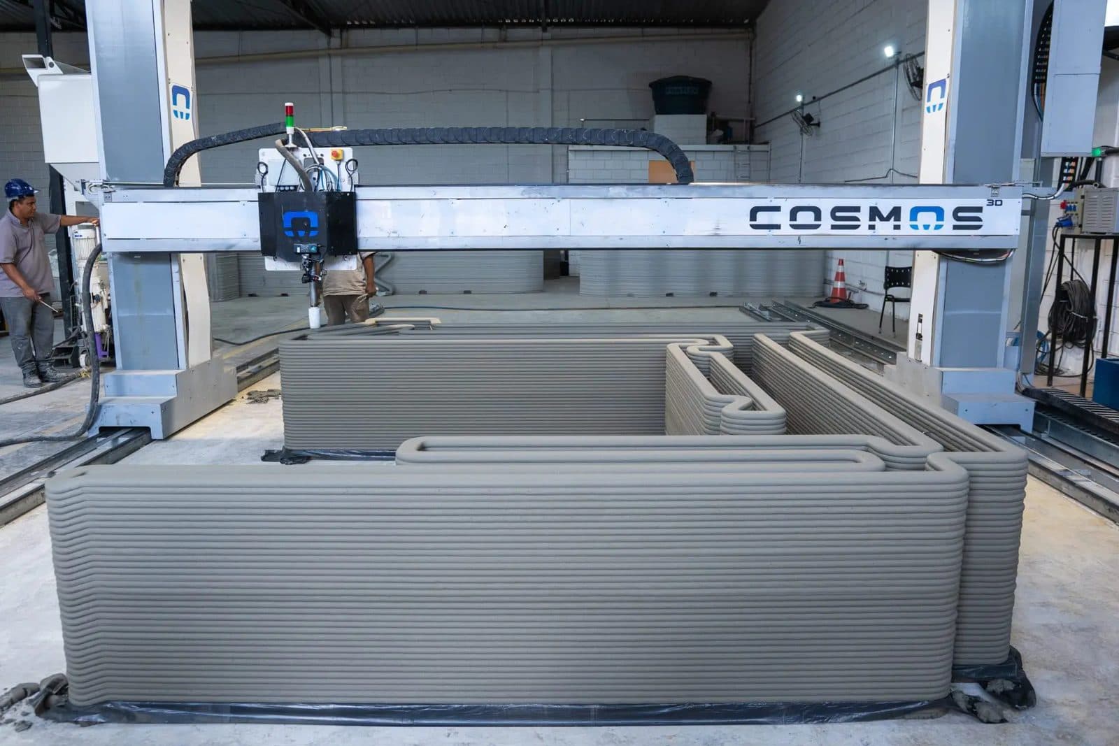
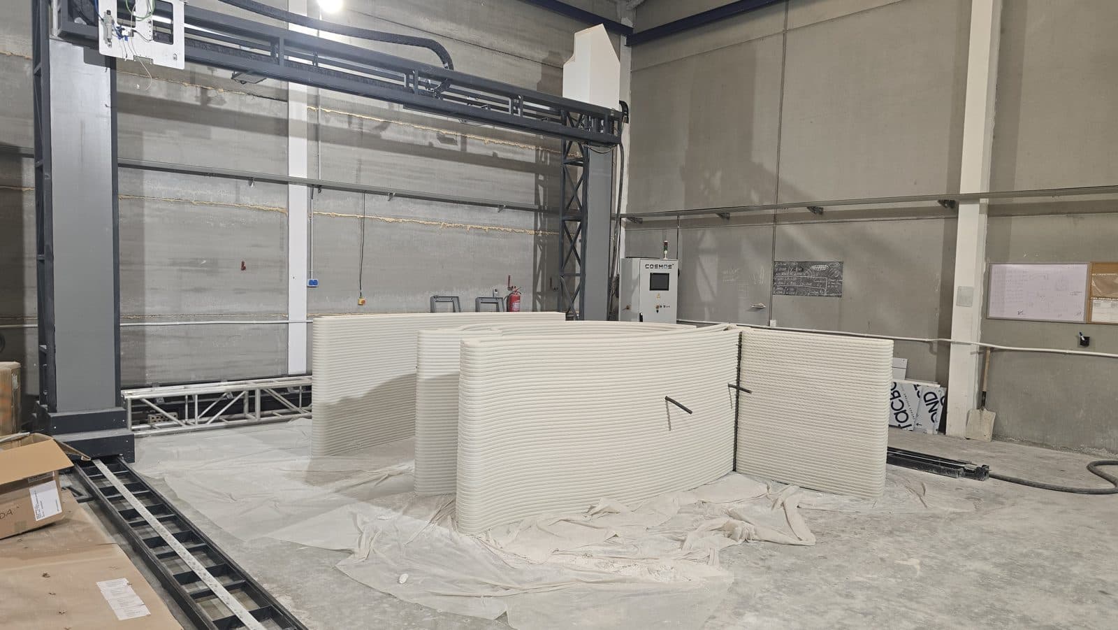
Source: the manufacturer's public datasheet. Real output depends on the design, the mortar and the conditions of each project. Formerly called X-I in the manufacturer's documentation.
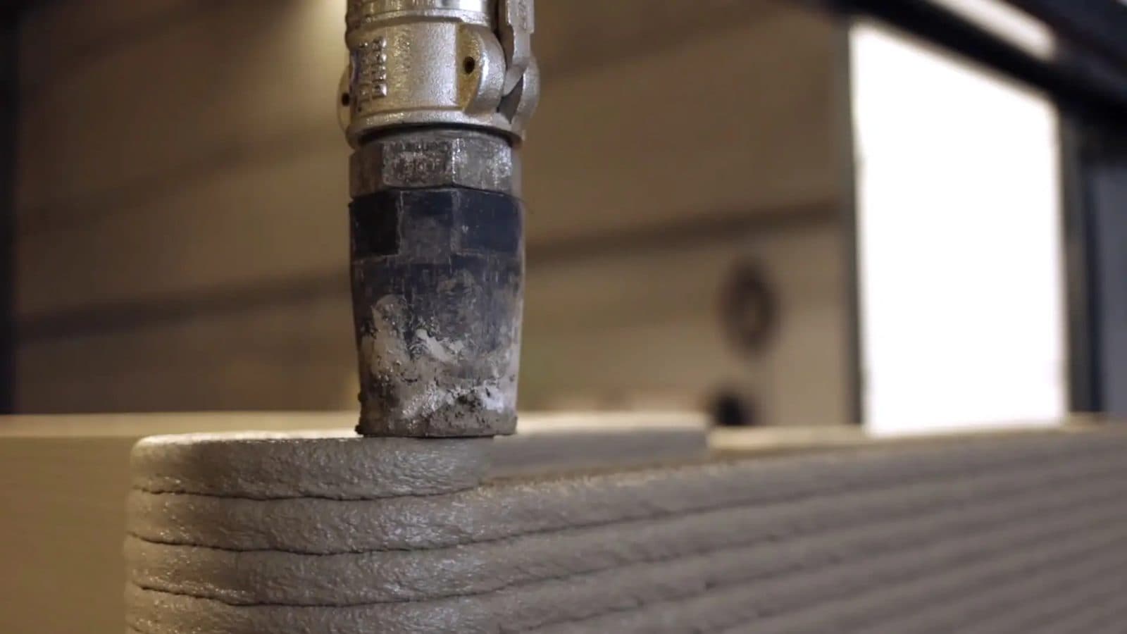
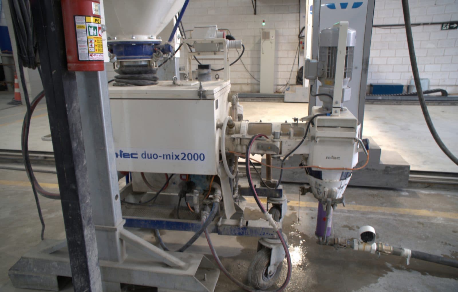
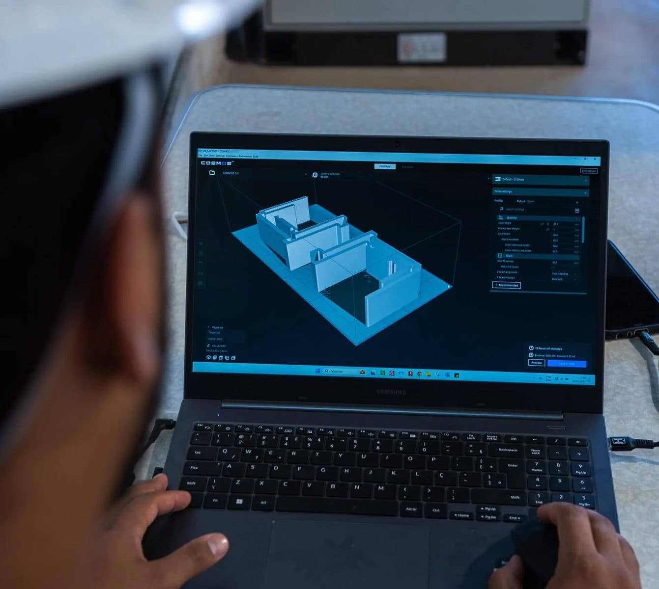
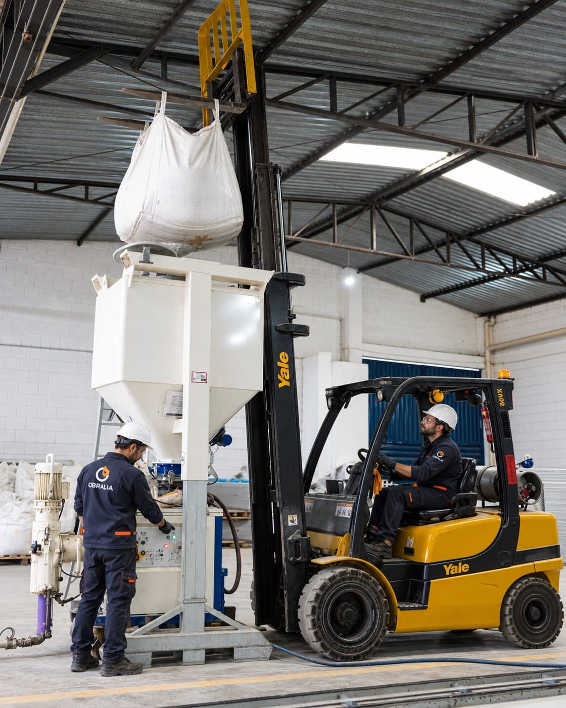
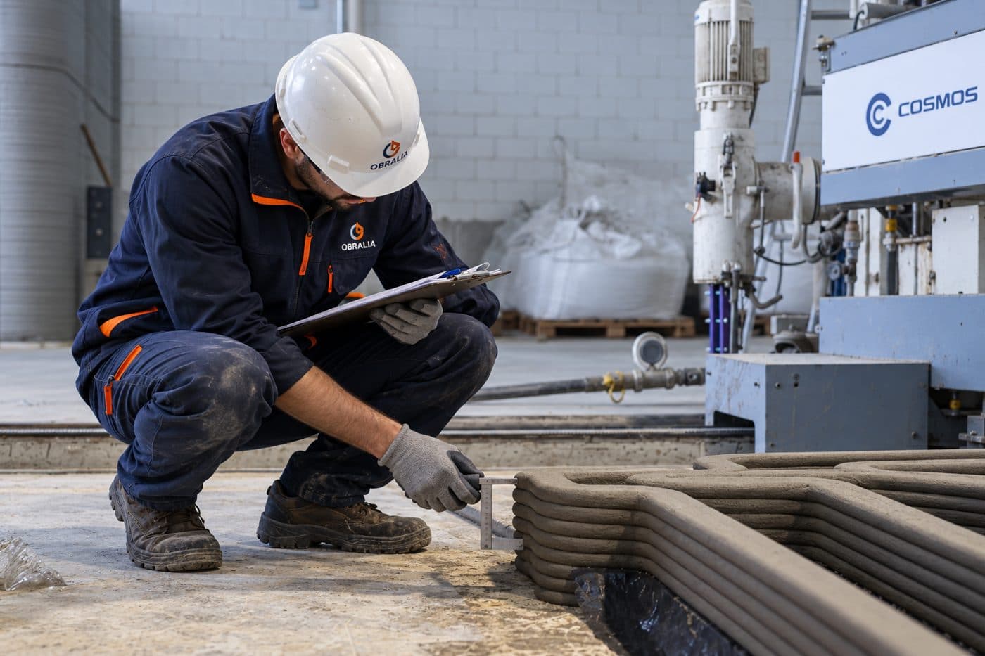
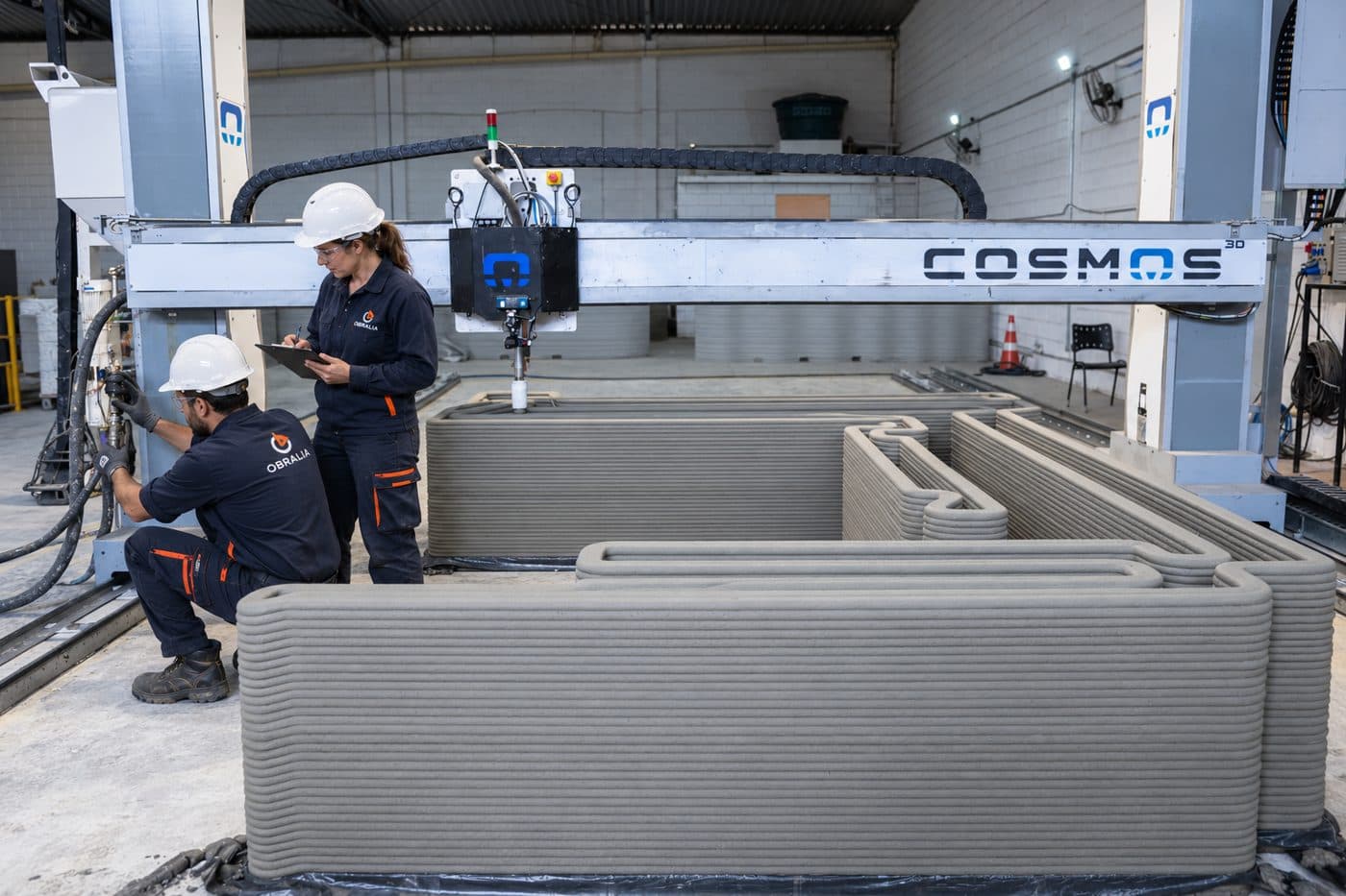
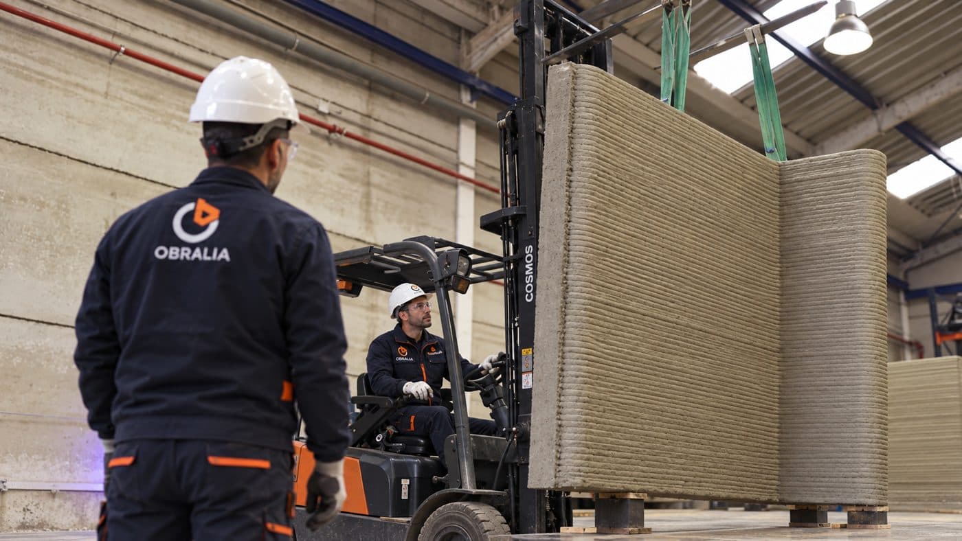
Photographs of the printer manufacturer's equipment and facilities and reference material on the technology. They are not projects built by OBRALIA 3D.
The manufacturer's own software (Slicer) turns the 3D model into print paths and controls the robot; a real-time dashboard shows material use, m² built, hours and stoppages.
We use the Holcim TectorPrint range of dry mortars, formulated for high-speed robotic printing, with colour built in through white cement and inorganic pigments.
Transparency: Holcim does not publish a TectorPrint datasheet with certified strengths. Before each project we request the datasheet and the batch certificate, and commission tests (EN 12390) on a printed test panel, with cores taken from the layer interface. Material and CO₂ reduction figures are published by Holcim, not tests of ours.
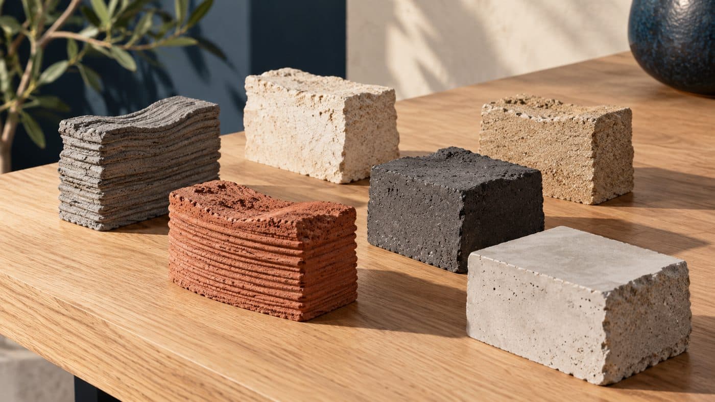
Colour is in the mortar itself, with no paint or later coating. Custom textures and tones can be defined.
While groundworks progress, printing already runs in parallel, in a factory hall or on site.
We review the plot, the brief and the regulations, and validate materials, loads and site logistics.
Basic and execution design, or adaptation of an existing design without altering its identity.
On site the foundations are excavated and poured while walls and pieces are printed.
The shell reaches handling strength in about 24 h (operating figure, to be confirmed per project).
Crane placement, reinforcement cages and pouring of the structural core.
Connection of accessible service ducts, finishes and final as-built documentation.
Our own engineering estimate for a two-storey detached house of 90 m² per floor, compared with traditional concrete and block construction.
| Construction phase | Traditional (days) | With 3D (days) |
|---|---|---|
| Earthworks and foundations | 24 | 10 |
| Structure and slabs (2 floors) | 82 | 10 |
| Envelope and façade | 18 | 0 |
| Interior partitions | 14 | 0 |
| Basic services | 10 | 5 |
| Interior finishes | 50 | 18 |
| Total (base programme) | 198 | 43 |
This is an estimate, not a guarantee: it assumes ≈718 m² of printable elements, production in parallel with the foundations, and 24 h shell curing versus 11–21 days per phase in traditional building. Real programmes are set in each project's feasibility study and exclude permits and contingencies.
Each project is defined, calculated and documented in an endorsed execution design, in line with the six basic requirements of the Spanish Technical Building Code (CTE).
Calculation and report for the reinforced-concrete core, signed by a competent professional.
Verification of the printed shell and core assembly.
Watertightness, moisture protection and ventilation.
Access, slopes and protective elements.
Verified acoustic insulation of the wall assembly.
Energy demand and thermal envelope of the system.
This is what we recommend demanding from any 3D-printing contractor.
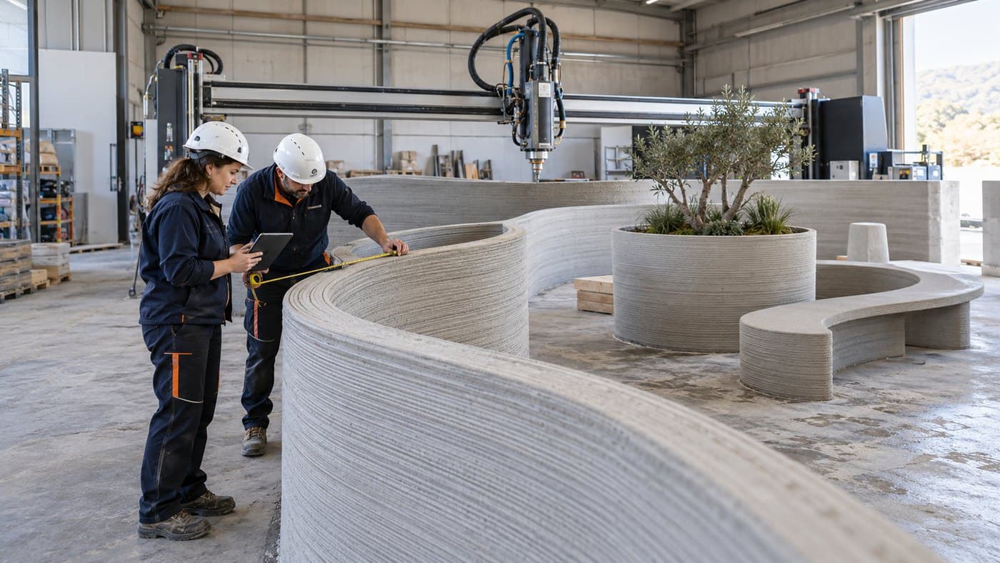
Curved walls and custom pieces without moulds.
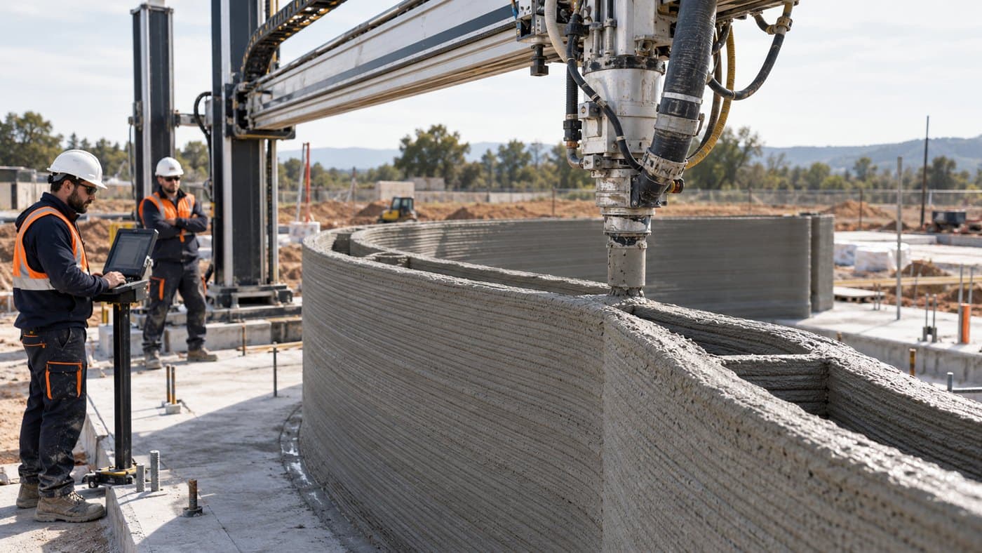
The shape is printed, so traditional formwork is reduced.
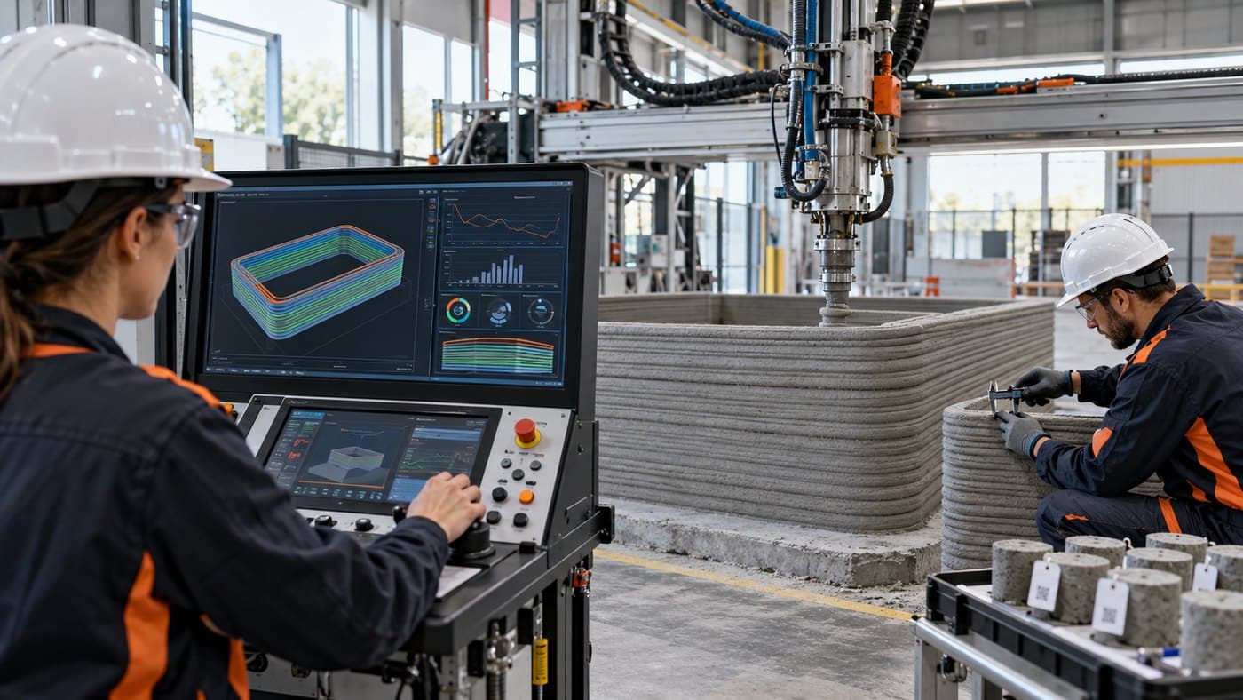
Better traceability of material and of each layer.
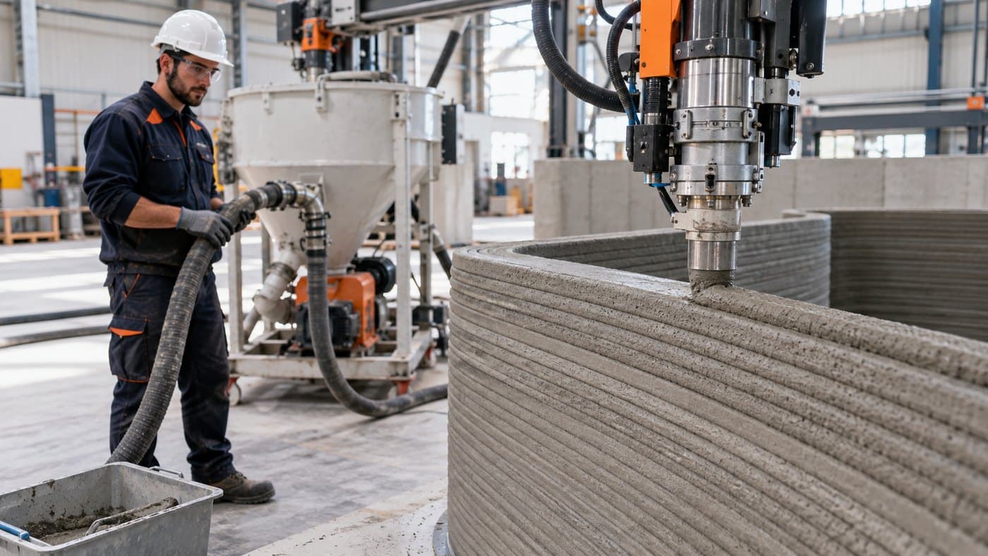
Only the material the design needs is deposited.
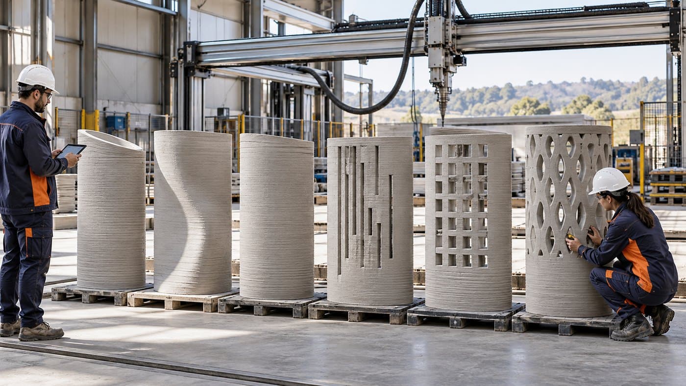
Series of pieces with defined variations.
Fewer manual operations and less stockpiling.
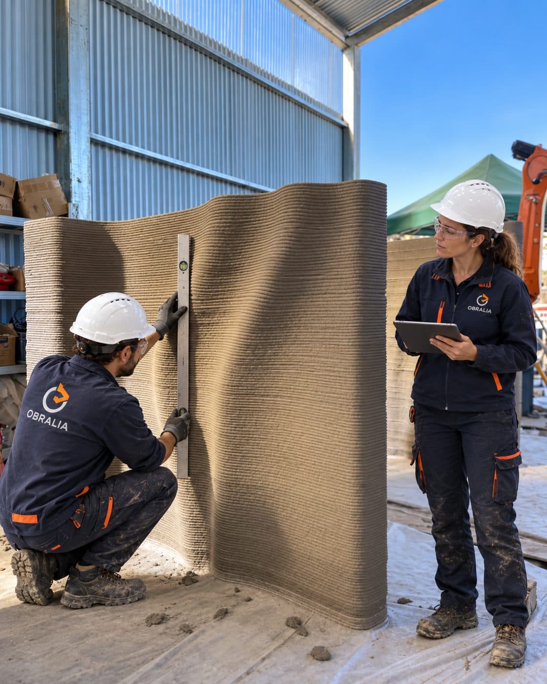
Illustrative, digitally generated visualizations; they do not depict completed works.
| Aspect | Traditional | 3D printing |
|---|---|---|
| Geometry | Limited by formwork | Free within design limits |
| Formwork | Needed for most walls | Reduced or absent in printed walls |
| Labour on walls | High and spread out | Small, specialised crew |
| Approval | Established regulations | Technical validation per project |
| Time and cost | Known in the market | Confirmed in the validation phase |
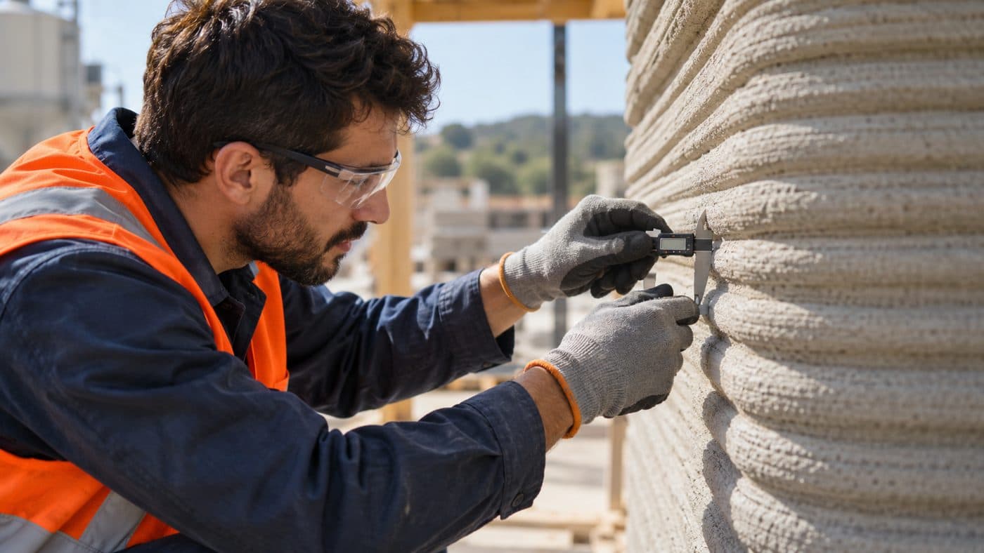
Illustrative images of the OBRALIA 3D process: fabrication, construction detail and applications.
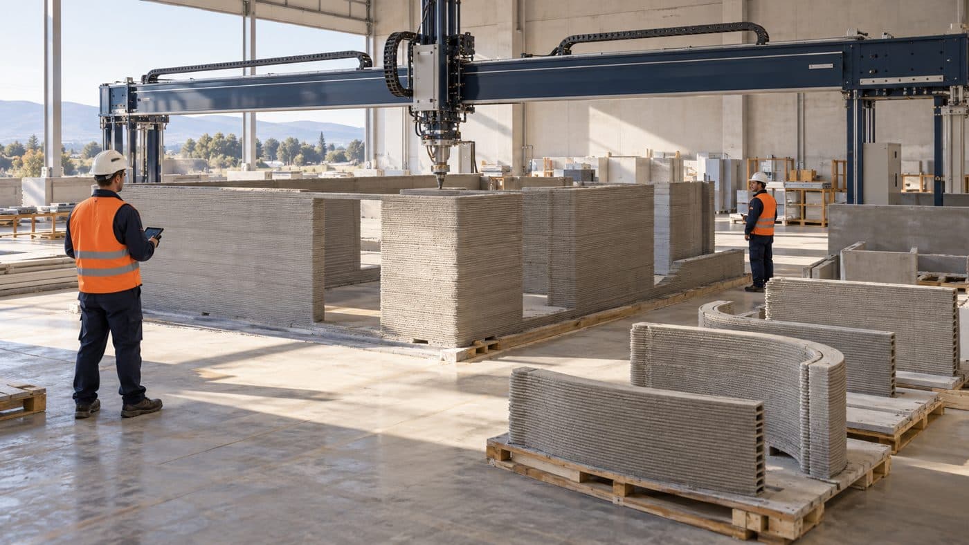
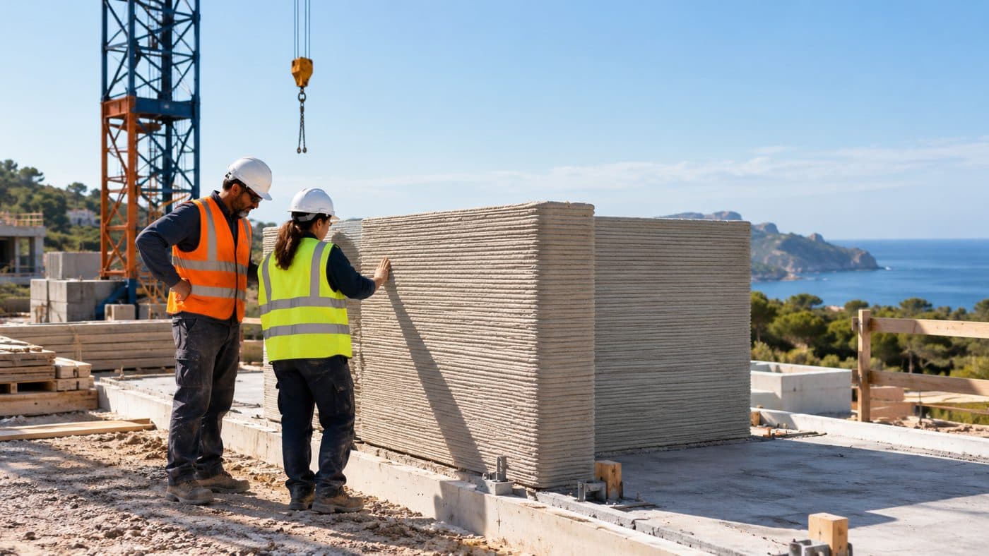
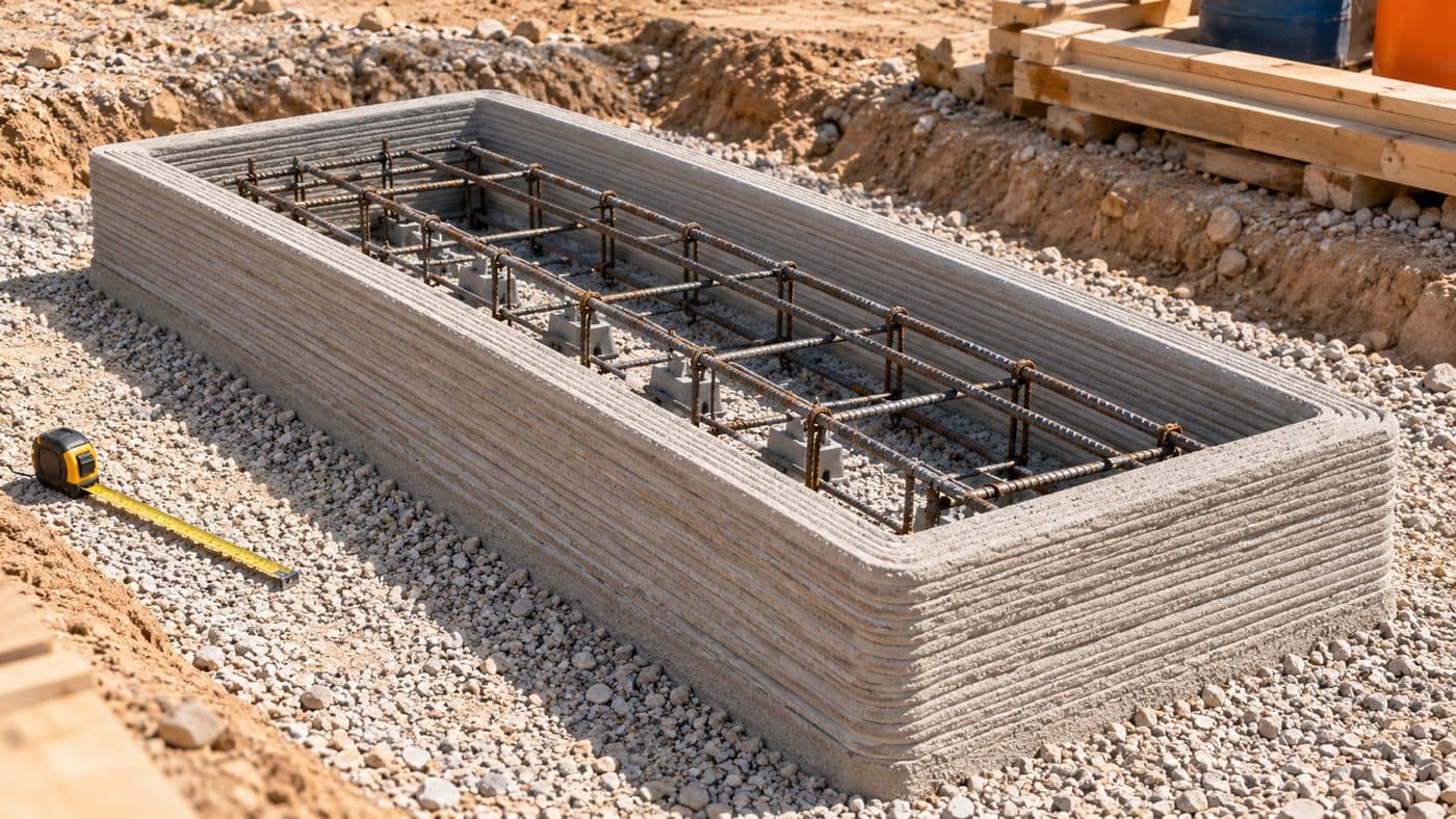
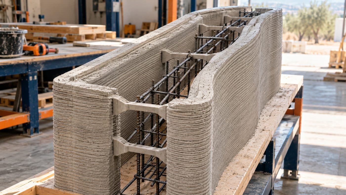
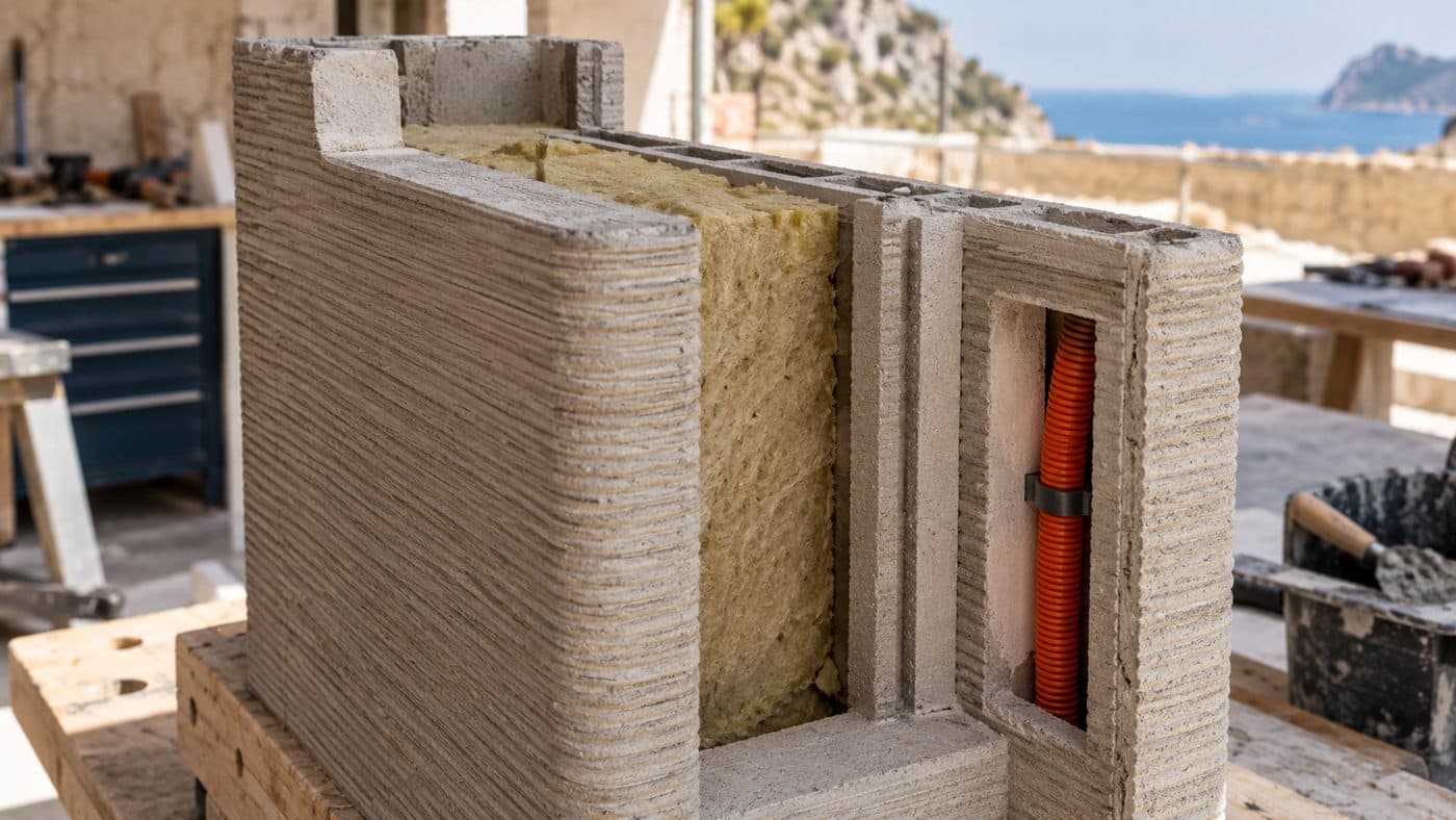
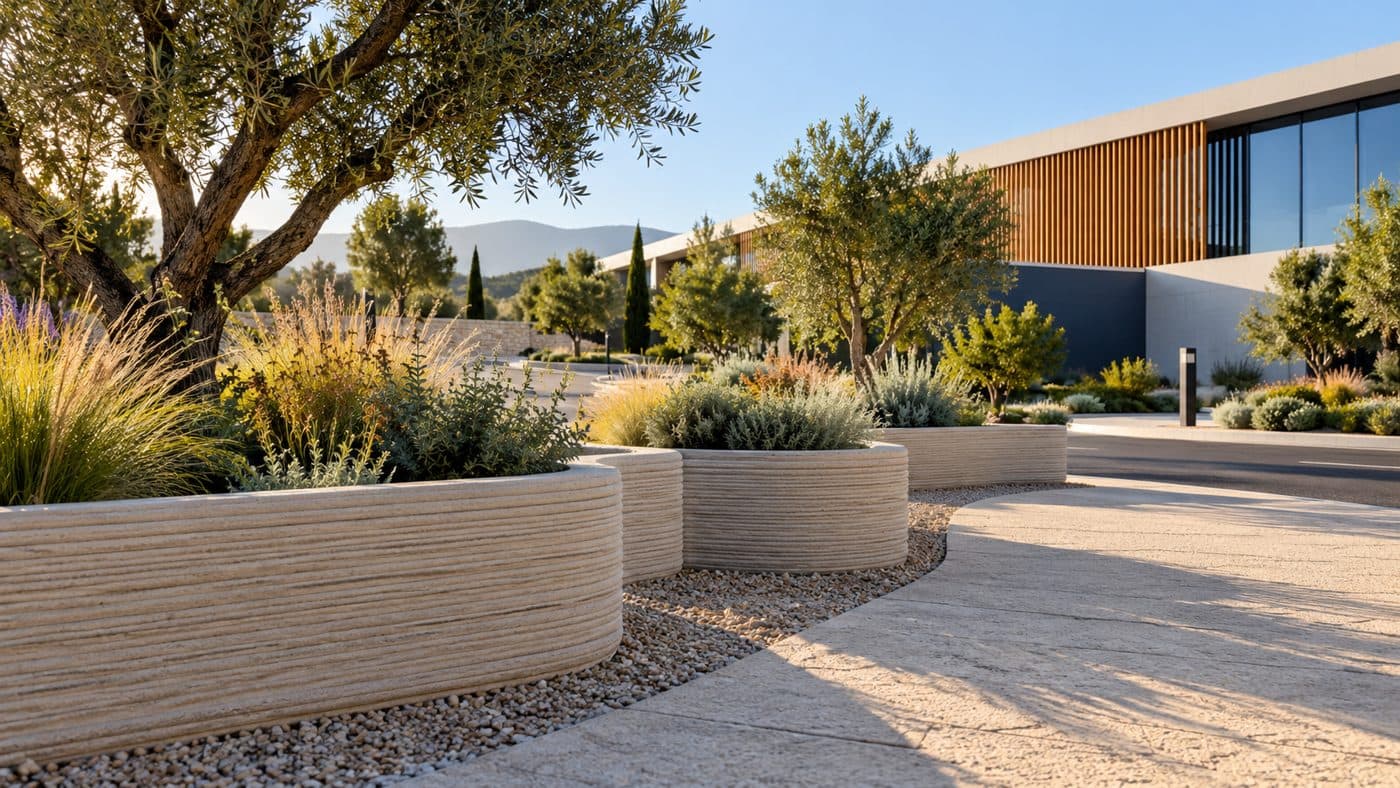
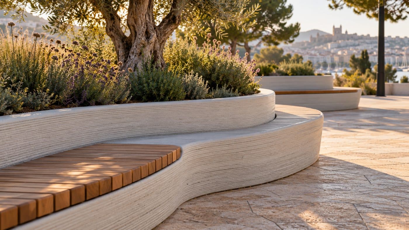
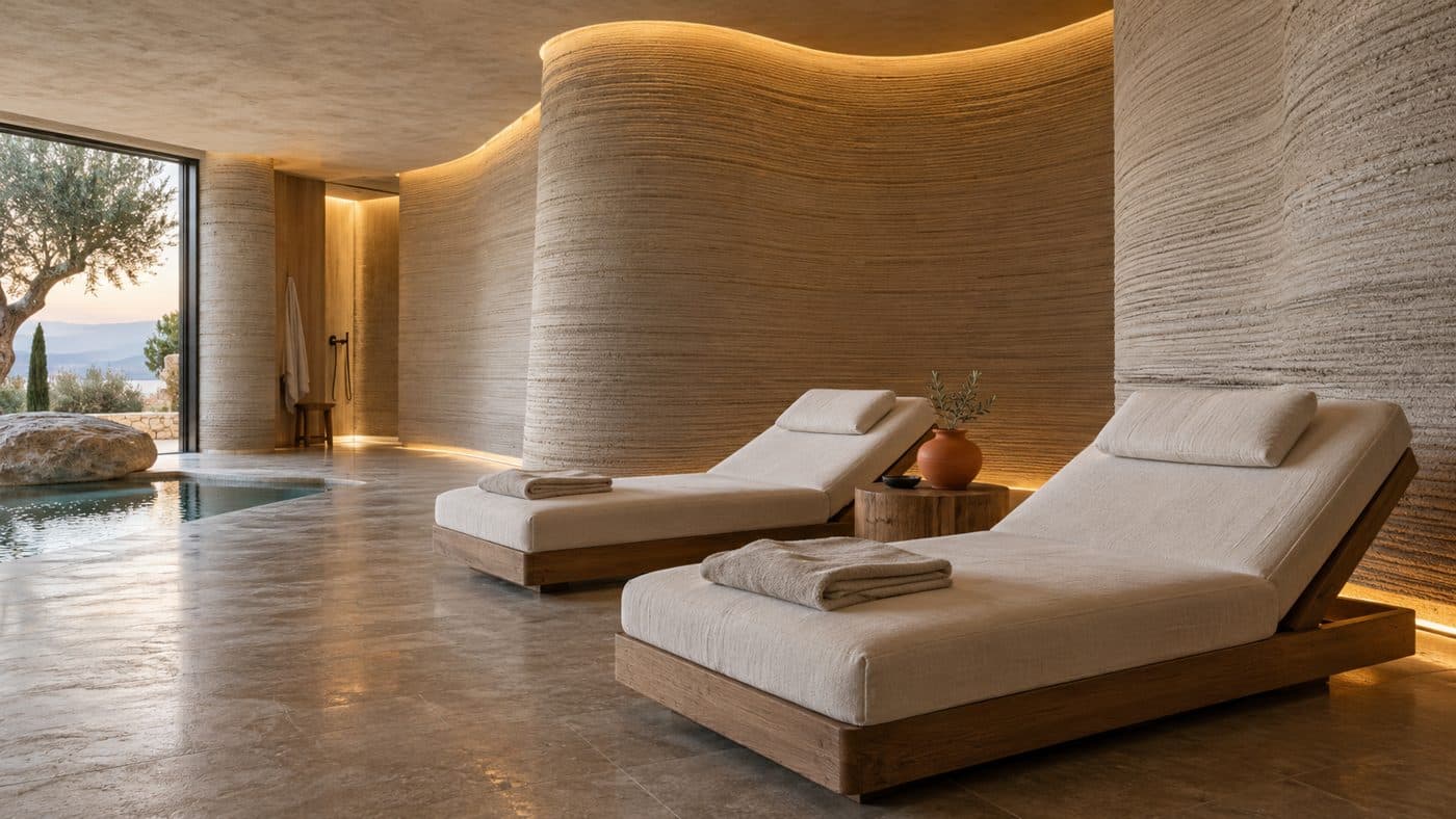
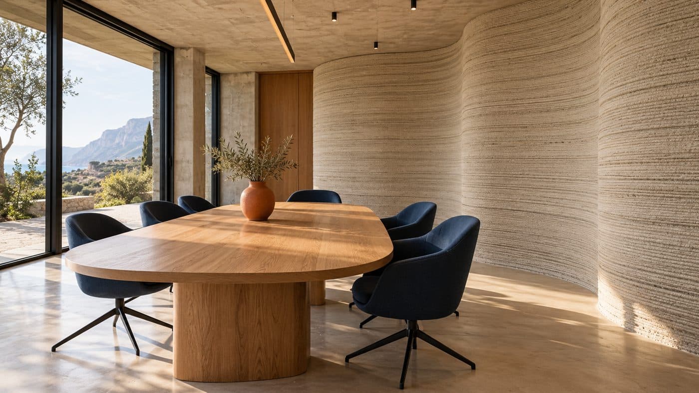
Illustrative, digitally generated visualizations; they do not depict completed works.